Week 1 : Creative Switch
Last week I watched the movie Tenete and I really liked it! It’s about a secret agent who manipulates the flow of time to prevent World War III. The Protagonist is employed by a secret organization called "Tenet," whose mission involves fighting the temporal war against the future. Members of the Tenet organization use a specific hand-clasped gesture to communicate, which represents the collision between the two directions of time.
The hand gesture inspired me. I decided to make a swith based on it: when I interlace my fingers, the switch turns on, and the LCD screen shows the word "TENET."
First I used Aluminum foil to make eight finger tubes. Then I connected the tube on my left index finger and the tube on my little finger into a simple LED circuit. Therefore, when I locked my fingers together, the eight fingertubes touched and conducted electricity, turning the LED on.


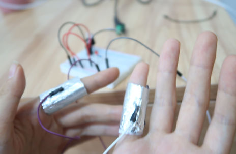

Next, I connected a LCD to my Arduino board and used simple code to print "TENET" to it. I moved the finger tube switch to this circuit and it worked out great! When I made the hand-clasped gesture, the LCD turned on and the word "TENET" was shown on the screen.

Week 2 : Digital I/O and Anolog I/O
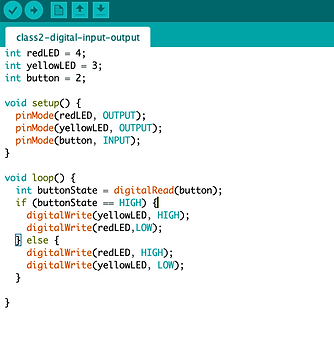
This week I learned how to program the Arduino to take inputs from sensors and program them to make stuff happen. In lab 1, I connected a digital input circuit and a digital output circuit to the Arduino. When I pressed the button, the yellow LED turned on and the red LED turned off. When I released the button, the red LED turned on and the yellow LED turned off.

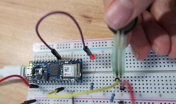
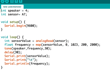
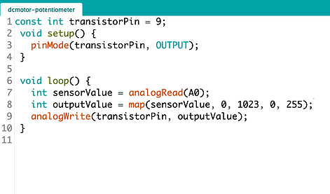
In lab 2, I used different sensors to control the brightness of the LED. First I started with a potentiometer. I used anologRead() to get the changing voltage over the potentiometer, and used map() and anologWrite() to convert that value into the brightness of the LED. So when I spinned the knob of the potentiometer, the luminance of the LED changed.


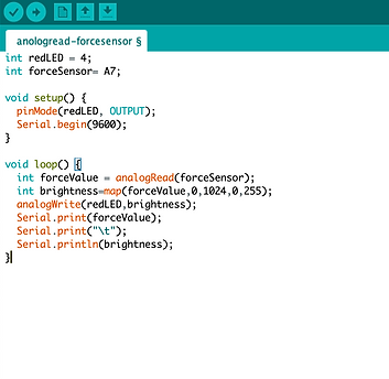
For the the force-sensitive resistor and phtocell, I put them into a voltage divider circuit to read their changing resistances. I also used anologRead() to get the changes, and used map() and anologWrite() to convert that value into the brightness of the LED.

[ Some questions about the voltage divider circuit: why does the input voltage equal to the voltage drop over the fixed resistor (at first I thought it equals to the voltage drop over the variable resistor)? How does the current flow in this circuit? Can we change the position of this two resistors? Why should the fixed resistor have the same order of magnitude as the variable resistor’s range? ]
When I pressed the FSR, its resistance decreased, the voltage drop over the fixed resistor (which is also the input voltage to the Arduino) increased, and accordingly the LED became brighter.
When I covered the photocell, its resistance increased, the input voltage to the Arduino decreased, and accordingly the LED became dimmer.


[ Qustion: After doing lab 2, I found that pin 4 is not a PWM pin, but anologWrite() worked and the LED changed its brightness. Why was that? Answer: Undocumented feature...Can use it as a PWM pin. ]
Week 3 : Tone Output and Servo Motor Control
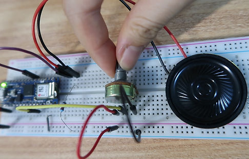
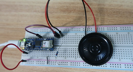
This week I learned to generate a changing tone on Arduino using the tone() command. I also tried to control a servomotor using the servo library.In lab 1, I used a potentiometer to change the frequency played on the speaker. After reading the analog input, I mapped the result to a range from 200 to 2000. Then I used the tone() command to set the frequency of the speaker. Thus, when I spinned the knob, the frequency changed between 200 Hz and 2000 HZ.
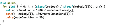
The pitch library makes it very easy to play a song on the speaker. Once you know the notes in a melody and duration of each note and rest, you can use tone command to play that song. In the lab, I played the Super Mario theme song on my speaker and it sounded good!
I also built a simple two-key keyboard with force sensing resistors. For each sensor, when its value goes above a threshold of 100, the speaker will play the corresponding note. [Question: when there was no delay between the two tone commands, one sensor didn't work properly. Why was that?]


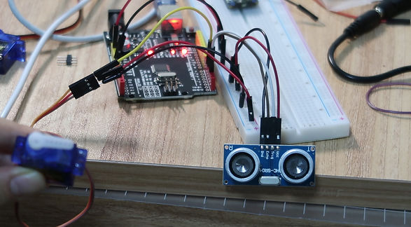
In lab 2, I used different sensors to control my servomotor. The force sensing resistor worked out fine but the ultrasonic sensor didn't work properly with the servomotor on Arduino Nano 33 iot. They both worked seperately, but when put together in one circuit, neither of them worked anymore, so finally I changed to Arduino Uno. [Solved: use Vin pin to get 5-volt output ]


When an object is more than 20 cm away from the sensor, the servomotor stays still. When an object is within 20 cm from the sensor, it turns 90 degrees.

Week 4 : Project 1 - MIDI Instrument
For our first project, Tora, Zhiyue and I decided to make three different instruments and play them together as a band! We planned to form a band that consists three instuments: guitar, piano, and drum. Guitar plays the main melody, drum plays the beats, and piano plays chords to complement the main melody. To achieve our goal, each of us set out to make a MIDI-instrument that has its own sound (guitar, drum, piano). For my instrument, I decided to make a Lauchpad-like MIDI controller using computer keys.

Ideation
There are 16 keys on the MIDI controller. The first 14 keys control different notes and the last 2 keys control the scale of the 14 notes. When one of the 14 keys is pressed, Arduino Nano will send a midi command to play a note on the computer. The midi messages can be converted into sound using digital audio workstations like Ableton Live.
Week 14: Final Project - MUSIC rings
2020/12/7
Prototype Testing
I wrote my code based on Tom's eight-key keyboard example and used 9 buttons to test it. The code worked: when I pressed the first button, the notes went one octave lower; when I pressed the second button, the notes went one octave higher; when I pressed one of the seven buttons on the right, the piano would play the corresponding note.

Ideation
Two problems occured in the process and I solved them with help from Tom:
Problem 1: If two keys are pressed at the same time, one note will not turn off.
Cause: In the original code, noteValue changes only if keyState is high, which means that when two keys are released at the same time, one key will not send the correct midi command.
Solution:: Change noteValue too if keyState is low or use midi command to turn all notes off when no key is pressed.
Problem 2 : After I press the buttons several times, the Arduino will stop communicating with the computer and the buttons will not work anymore.
Solution: Remove the serial1.write() command which is causing the problem.
Soldering and Mounting


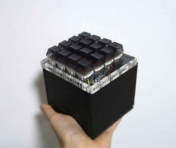
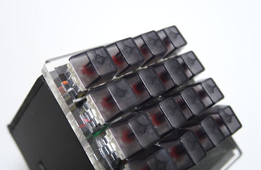
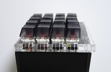
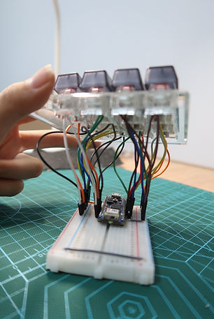
Then, I soldered wires to the 16 buttons and placed them on a 4x4 keyboard tester kit. This was actually the the most time-consuming part of the process. (P.S. I was burned by the soldering iron twice.)


The Circuit and Code
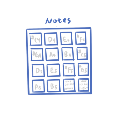
For each key, I connected one side to a digital input pin of Arduino Nano, and the other side to ground. All pins were set to INPUT_PUllUP mode. In the code, I mapped the first 14 keys to a default scale from #C4 to B5. When I press the penultimate key once, the scale will change to #C3 to B4; when I press the last key once, the scale will chage #C5 to B6. In this way I can play the song Dance Monkey quite easily.

Check out the code here.
Final Assembly
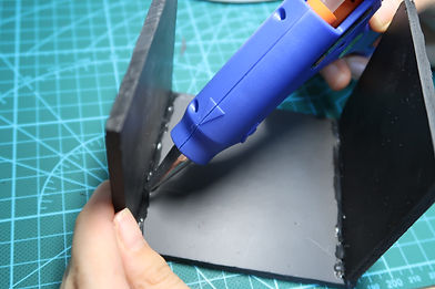
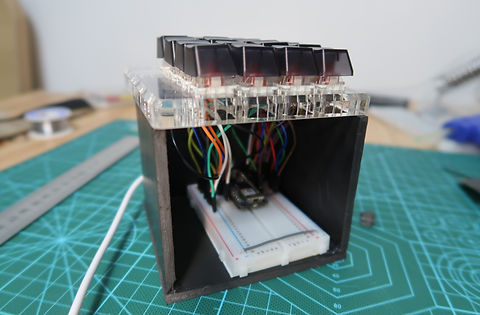
At last, I made a case out of PVC board and put the electronics inside.
Now I have a MIDI instrument! Hooray!!

Final Product

Show Time!
- Solo Performance -

- Band Performance -
Thoughts
1. It's amazing that our group learned MIDI, made all the instruments, played a song together, and made a video in just ONE week! I'm so proud of my group.
2. Playing music is so fun. I'm planning to learn more about MIDI, music composition, music production, etc. Hopefully in the future I can make real music projects and perform them with my MIDI controller.
3. The next step for this project will be adding potentiometers or sliders to control volume, frequency, effects, etc.
Week 6 : Asynchronous Serial Communications
Serial Input to P5.js in Binary (Single Value)
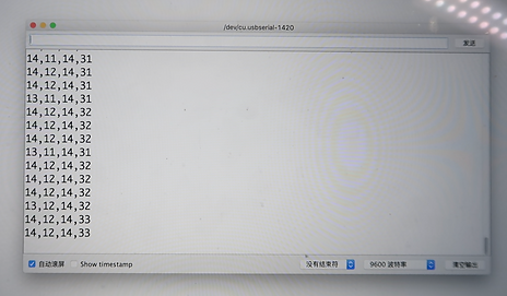
On the Arduino side, I connected the X pin of the joystick to Arduino's pin A0 and used AnologRead() to get the input value. I mapped the X value to 0~255 so that it could fit in one byte, and sent the data out to p5 using Serial.writea(). On the p5 side, first I added the P5.js serialport library to my sketch and installed the p5.serialcontrol app to enable communication between the browser and the microcontroller. Then, I added serial.read() in the serialEvent() function to read the incoming data from Arduino one byte at a time. I stored the incoming data in a global variable and used it for the ball's x position. In this way, I was able to move the ball horizontally with my joystick.
Serial Input to P5.js in ASCII (Multiple Values)
Next, I wanted to send data from multiple sensors, so I connected X pin of the joystick to Arduino's pin A0, Y pin to pin A1, and switch to pin 8. This time I didn't need to I map each sensor‘s value to 0~255 because I was using the Serial.print() command which could send the data as an ASCII-encoded numeric string. To send three sensor values at a time, I put a comma between them and termination punctuations at the end (newline and carriage return).
On the p5 side, I used serial.readLine() in the serialEvent() function to read the incoming ASCII-encoded strings from Arduino. If the string had a length greater than 0, the split() function would split it in to an array of strings. If the resulting array was three elements long, I converted each element into a number using the Number() function and thus I had my three sensor readings. I stored the readings in three global variable and used them for the ball's x position, y position, and visibility. In this way, I was able to move the ball around the screen and change its visibility with the joystick.
Serial Output from P5.js in Binary (Single Value)
In p5, I mapped mouseY to a value form 0 to 255. Then I used serial.write() to send that data to Arduino. On the Arduino side, I connected a LED and a resistor to pin 6. In my Arduino code, I used Serial.read() to read the incoming data from p5 when there was serial data available. I stored the data in a variable and used it to set the LED brightness with AnalogWrite(). In this way, I was able to light or dim the LED by moving the mouse vertically.
Serial Output from P5.js in ASCII (Multiple Values)
Further on, I wanted to have two LEDs and use mouseX and mouseY to control their brightness respectively, so I connected another LED to Arduino's pin 6. In p5, I used serial.write() to send the mouse position as an ASCII-encoded string. To send mouseX and mouseY together at a time, I put a comma between the two values and a new line character at the end.
On the Arduino side, I used serial.parseInt() to separate the incoming ASCII-encoded string by comma, and read the information into variables "inDataX' and 'inDataY'. Once serial.parseInt() found a newline character at the end of a string, analogWrite() would change the brightness of the two LED respectively. When I moved my mouse from left to right, the yellow LED became brighter; when I moved my mouse from top to bottom, the red LED became brighter.
Week 8 : Synchronous Serial Communications
I2C Communication with APDS-9960 Sensor
To communicate with a color, gesture, and proximity sensor from my Arduino, I connected the sensor's SDA (I2C serial data) pin to Arduino's pin A4, SCL (I2C clock) pin to Arduino's pin A5, and the sensor’s voltage and ground connections to the voltage and ground buses. The color sensing example sketch worked fine, while the gesture sensing example did not work.The sensor initialized correctly, began to work, but did not recognize any gestures. I searched the internet and found that many people encountered the same problem. Tom said it had to do with the sensor itself.
color sensing
SPI Communication with SD Card Reader

gesture sensing
To communicate with a SD card reader from my Arduino, I connected the reader's CS pin to Arduino's pin 10, SCK pin to Arduino's pin 13, MOSI pin to Arduino's pin 12 (SDI) , MISO pin to Arduino's pin 11 (SDO) , and the sensor’s voltage and ground connections to the voltage and ground buses. Unfortunately, the SD card didn't show up on my Macbook pro. When I ran the Cardinfo example sketch, it showed"Wiring is correct and a card is present", but in Desk Utility and Finder I coundn't find the card and thus I couldn't format it. So sad :(


Week 9 : Project 2 - Star Machine
Leveraging physical computing, creative coding, and machine learning, I made a star machine that lets people experience the joy of catching a star of their own✨
Concept

1
2
3
4
When a player stands in front of the star machine, the computer will track his/her right hand through webcam using the PoseNet machine learning model.
If the player's hand reach a star, the star is "captured" and it will follow his/her hand.
When the player place the star inside the crystall ball, the star will gradually disappear and at the same time p5js will send a signal to Arduino.
After receiving the signal, Arduino will turn the LED string on and make the sttepper motor rotate one revolution, so that one star candy fall out at a time.
Prototype
First, I built a prototype using carboards and bamboo sticks. The mechanism was inspired by a DIY vending machine tutorial.

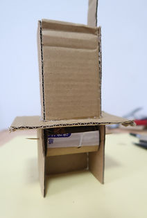


Next, I glued a stepper motor to one side of the stick and programmed it to rotate one revolution when Arduino receives a byte. When the motor makes one complete rotation, the basket will also rotate 360 degrees and one candy container will fall out at a time. I chose to use stepper motors because they can be turned in very accurate steps,
whereas DC motors turn continuously.
In retrospect, gluing the motor and the stick was not a good solution. Tom suggested that I could consider using a shaft coupler next time to make the structure more secure.
Code
In the p5 sketch, I drew stars at the top and a circle at the bottom to represent the crystal ball. I used PoseNet to track a person's right hand and calculated the distance between the player's hand and the star, and also the distance between the star and the circle. If the player's right hand is close enough to a star, the star's xy position will be the same as the hand's. If the star is inside the circle, it will gradually disappear and p5js will write a byte to Arduino at the same time. After reading the incoming byte, Arduino turns the LED string on and makes the sttepper motor rotate one revolution. Here's the basic logic of my code:
Action

Catch a star
Put the star in the crystal ball
The star disappears
LED lights up,
a candy falls out
Code
distance1 = dist ( handx, handy, starx, stary );
distance2 = dist ( starx, stary, circlex, circley );
if ( distance1 < 25 && distance2 > 25 ) { capture = true; }
if ( capture ) { starx = handx; stary = handy; }
if ( distance2<25 ) { capture=false; }
if ( !capture && count==0 ) { serial.write ( 1 ); count++; starDisappear ( ); }
if ( star.pixels [ alpha ] >0 ) { star.pixels [ alpha ] --}
if ( incomingByte == 1) {
for ( int i = 0; i < 255; i ++) { analogWrite ( 6, i );}
myStepper.step ( stepsPerRevolution );
for ( int i = 254; i >= 0; i --) { analogWrite ( 6, i ); } }
I connected my computer and the Arduino to test the program. It turned out to be pretty good. Here's the demo video and the complete code:

Assembly


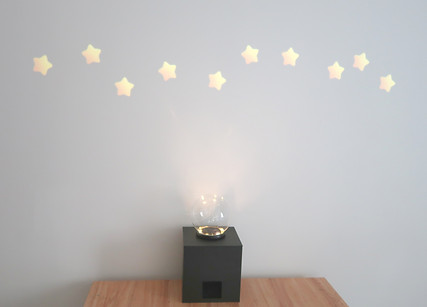
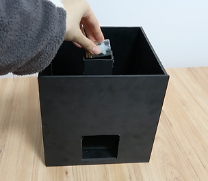
For the final product, I used black PVC boards to make the inner structure and the case. I cut a square slot off the front board and placed the LED string around the slot. I also made a slope so that candies could land right behind the slot. After putting all the electronics and the candies inside, I covered the case with a lid and put a crystal ball on it. At last, I connected the microcontroller, webcam, and projector to my computer and pojected the p5 sketch on the wall.
Final Product

Week 10 : Motors
Controlling a DC Motor with a Transistor
In lab one, I controlled the speed of a DC motor using a FQP30N06L MOSFET and a potentiometer. I connected the first wire of the DC motor to the drain of the transistor and the second wire to the 3.3v pin of the microcontroller. The source of the transistor connected to ground and the gate connected to Arduino's pin 9. In the code, I read the voltage of the potentiometer and mapped the result to a range from 0 to 255. Then I used that value to set the speed of the motor with analogWrite().

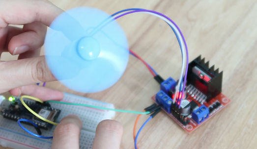
Controlling a DC Motor with an H-Bridge
To control the motor's direction, I used the L298N module I had at home. I connect the VCC terminal of the L298N module to external 12V power supply and the input and enable pins(ENA, IN1, IN2) to three Arduino digital output pins(5, 4,3). Then, I connected the motor to terminal A(OUT1 & OUT2). I also added a button to control the motor's spinning direction.

Controlling a Stepper Motor with an H-Bridge
I also used the L298N module to control a stepper motor. As L298N module has two H-Bridges, each H-bridge can drive one of the electromagnetic coils of a stepper motor. By energizing these coil in a sequence, the shaft of a stepper can be moved forward or backword precisely in small steps. I connected the input pins(IN1, IN2, IN3 and IN4) of the module to four Arduino digital output pins(5, 4, 3, 2). Then I connected the A+,A-,B+,B- wires from the stepper motor to the module as shown below.


Week 14: Final Project - MUSIC rings
2020/12/9
Music Rings is an interctive interface for music performance. It allows users to play music with ther hand movements.
Ideation

I've been interested in gesture/motion-based interafaces for musical performance and how they translate physical movements into audio outputs. I've made web-based games which use the user's motion to generate music before and for my final project, I wanted to add some physical elements to it. I decided to create an interactive interface that allows performers to control music and lights with their hand movements.
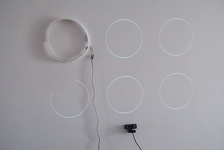
The installation consists of 6 rings, each of which is made up of a 70 cm long LED strip and a piece of foam board. All the rings are stuck on a wall and controlled by Arduino. A p5 sketch is projected on the wall and mapped to the rings. A webcam is placed below the rings to track the permormer's hand positions.
When the performer's hand position moves inside a ring, the LED strip will light up and a music clip will be played. When the performer's hand moves out from the ring and then goes inside again, the LED strip will turn off and the music will stop.
Coding & Testing
In the p5 sketch, I created 6 circles to represent the music rings. Each circle is associated with a specific music audio file (bass, mallet, etc). Inside each circle there's also a solid colored circle which acts as the music visualizer. Its size is related to the audio's amplitude. I used the machine learning model PoseNet to detect hand positions and used two white solid circles to indicate where the user’s hands are located. When the user's hand moves inside a ring, p5 will play the associated music clip and send a start signal to Arduino to turn on a LED strip. When the user's hand moves out form the ring and comes back again, p5 will stop the music clip and send a stop signal to Arduino to turn off the LED strip. On the Arduino side, I used the FastLED library to control the 5-volt WS2812 LED strips. When a music clip is playing, the corresponding LED strip will show a running light effet with a fading trail. Here's the demo video:


Fabrication
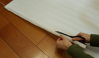
For each LED strip, I extended its wires, stuck it on a strip of foam board, and glued the two ends togeter to make a ring. Then I projected my p5 sketch on the wall and stuck the rings according to the positions of the projected circles. The 6 LED strips are in parallel in the circuit and I used a 5V/6A adaptor to power them.


Final Product

